Vector Logos in F360 Electronics Workspace
in Modeling on October 2, 2021 | Electronics Fusion 360 Eagle Illustrator Inkscape
I was working on my latest project which includes another PCB. I whipped up some vector art that I felt suited my project well and was quickly thwarted by the incredibly poor support for importing shapes into the F360 Electronics workspace.
Eventually, I was able to succeed using the following steps:
- Expand into minimum polygons
- Export to PDF
- Open in Inkscape
- Increase node count
- Flatten bezier curves
- Cut open holes
- Ungroup everything
- Scale your Artwork
- Save as DXF
- Run ULP
- Convert to polygons
- Export only polygons that are not touching
I usually work in Illustrator but I was unable to accomplish a couple of the most important steps above. As usual, Inkscape shines when your needs are more technical than artistic. As such, this process will span both apps but the Illustrator steps all have pretty obvious alternatives in Inkscape if you prefer.
In general, these steps are order dependant. If you are having trouble you may be more successful starting over than trying to undo any history.
Expand into minimum polygons
This process is only going to support Fills. Use Object -> Expand to turn your Strokes into actual polygons.

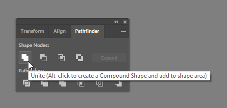
We also need to make sure we have as few polygons as necessary. Bring up the Window -> Pathfinder and use the Unite shape option to eliminate any overlapping geometry.
Export to PDF
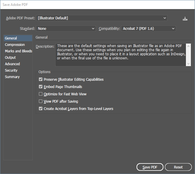
I often like to export into PDF for maximum compatibility when leaving the Adobe ecosystem. For me, the defaults were fine.
Open in Inkscape
We need to move over and open our work in Inkscape to make use of the Increase node count and Flatten Bezier features. If anyone knows of a good way to do these steps in Illustrator, leave a comment.
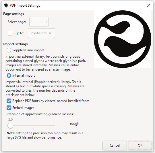
For the import, the defaults worked for me.
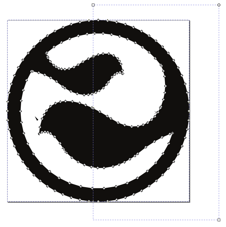
Increase node count
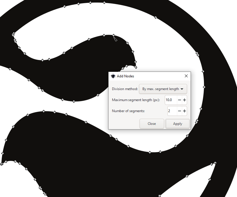
Select your polygon(s) with the Node selector tool. Use Extensions -> Modify path -> Add nodes. The defaults are a good place to start but in my experience this is the most finickey steps. Too few points and your art will look poor while too many siezes up Fusion. The Flatten step also adds points, so you can also try leaving this step out altogether.
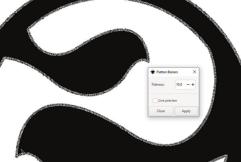
Flatten bezier curves
With your polygon(s) selected, use Extentions -> Modify path -> Flatten Beziers. Again, the defaults worked for me.
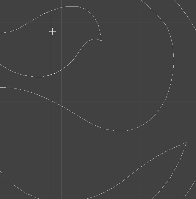
Cut open holes
When we finally do the import to Fusion, we will eventually need to run a convert to polygon operation. Unfortunately for us, this operation does not support polygons with holes (nested shapes). As a work around, we will cut any shape with a hole into two concave polygons.
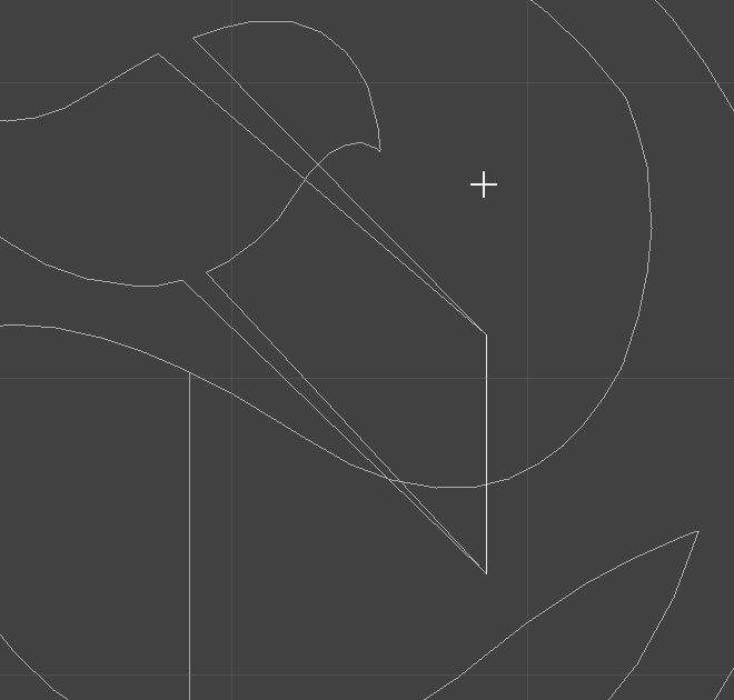
To do this, draw a rectangle through your enclosed shapes.
With all your shapes and the rectangle selected, use Path -> Divide.
Ungroup everything
Select everything and repeatedly Object -> Ungroup until there are no groups left.
Scale your Artwork
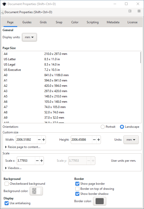
Go to File -> Document Properties and set the Display units and Units to mm.
With the regular Selection tool, select everything and uniformly scale down to your desired size in millimeters.
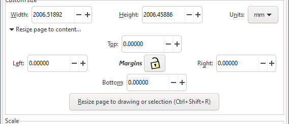
Go back to File -> Document Properties and under the Resize page to content... dropdown, click Resize page to drawing or selection.
Save as DXF
File -> Save as -> DXF R14. Remember to set your Base unit to mm.
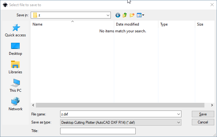
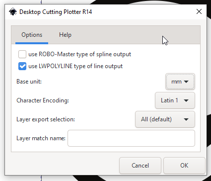
Note: File -> Save for some reason, will not work. You must Save as.
Run ULP
Now it’s time to get our electronics project open in Fusion. You can import these polygons directly into one of your board designs or into a footprint of a device in your library.
Once you’re in your board or footprint, go to the Automate tab and find the Run ULP button in the ribbon.
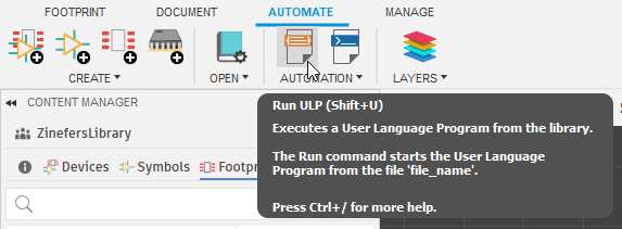
Click it and search for the import-dxf ULP. Select it and click OK.
Here you will select your DXF file and scaling options.
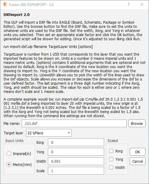
After clicking OK, a new window will appear with a script that has been generated. Click Run.
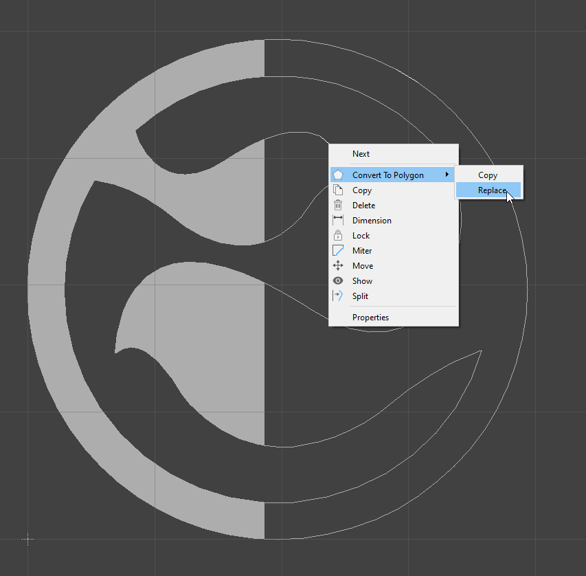
Convert to polygons
Right click on each polyline and Convert to polygon -> Replace.
If the process takes a long time, consider changing the settings for the Add nodes or Flatten steps.
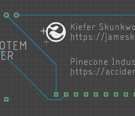
If all went well, you should now be able to move your artwork onto your board, or in the case of a device, add the device to the schematic and then move it around your board. If not, see below.
Export only polygons that are not touching
I found that some art, after being cut would at some point would rejoin the overlapping line. The Convert to polygon feature does not work with T junctions, which is what these lines that get rejoined become. You can test for this, after an import by grabbing the borderline and moving it.
A workaround for this, is multiple dxf files that each only contain polygons that do not touch. Run the Convert to polygon before importing any other


Thank you
Your comment has been submitted and will be published once it has been approved.
OOPS!
Your comment has not been submitted. Please go back and try again. Thank You!
If this error persists, please open an issue by clicking here.
Say something