Promini Stepper Controller
in Hardware on September 23, 2018 | Electronics Robotics Arduino Soldering Prototyping Desk Lift
Prototyping
I worked on this on an off for the past couple of weeks. Using the A4988 product page I had this functional on the breadboard pretty quickly.
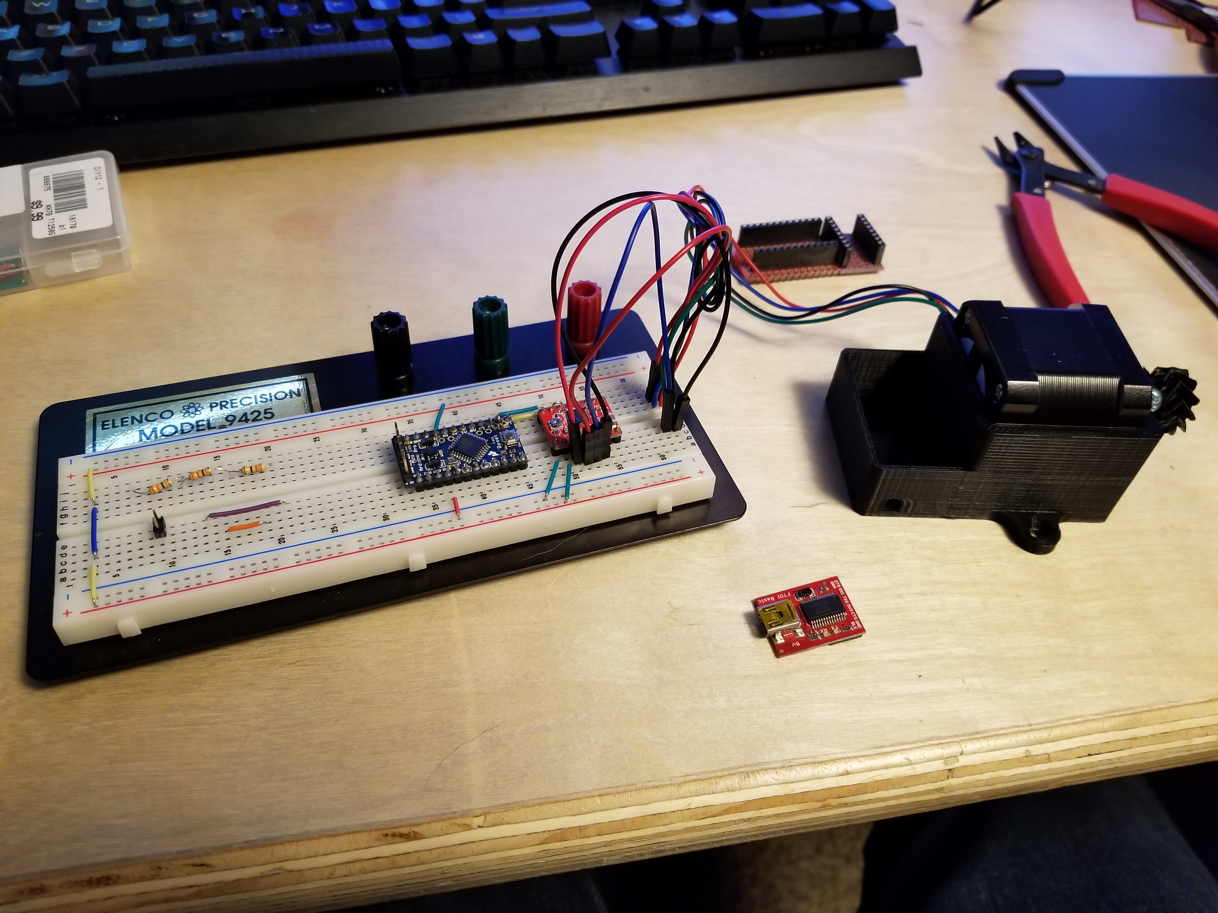
I was running things off two separated power rails here and forgot about it after getting excited and plowing through to a premature prototype phase.


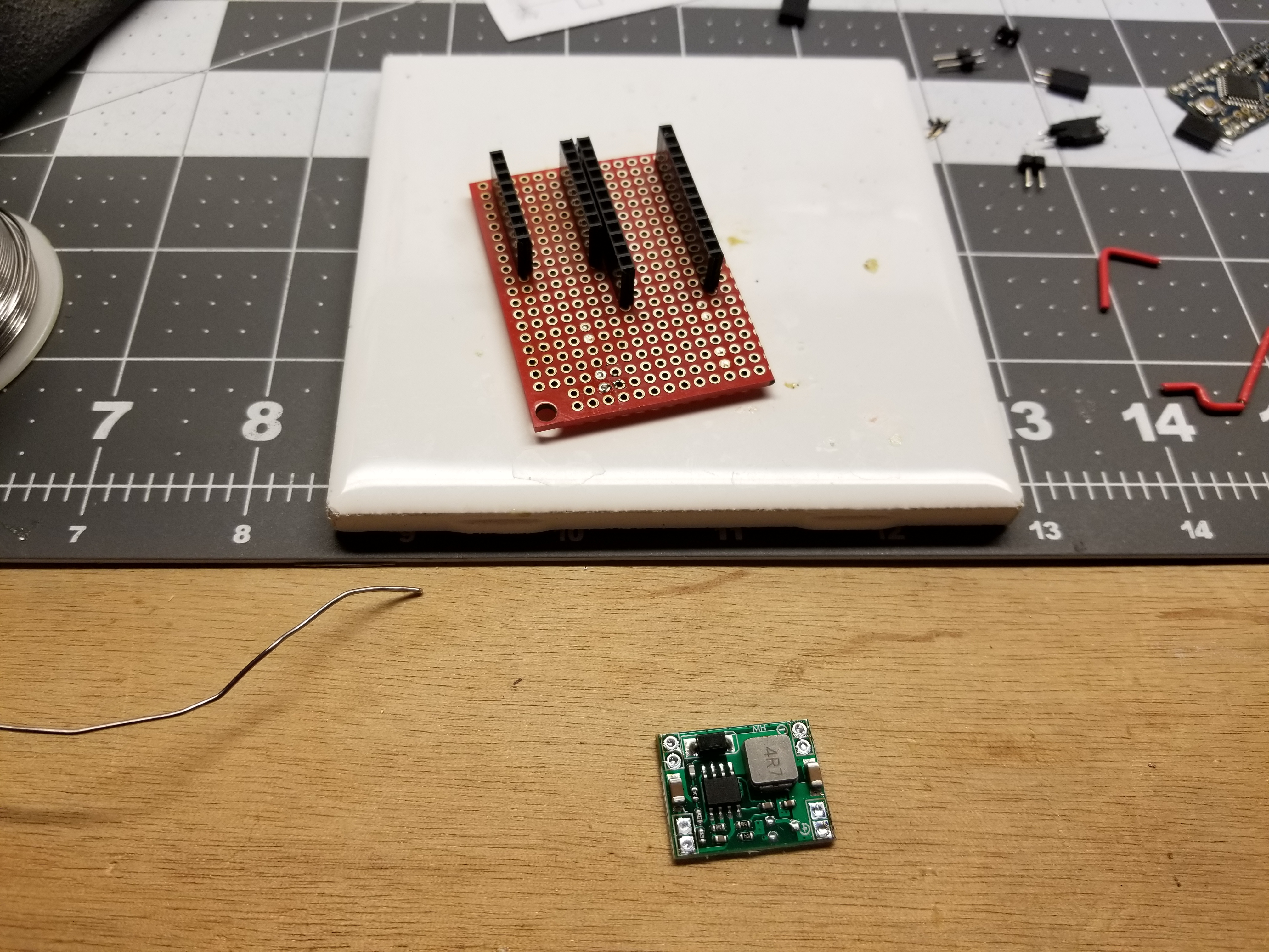
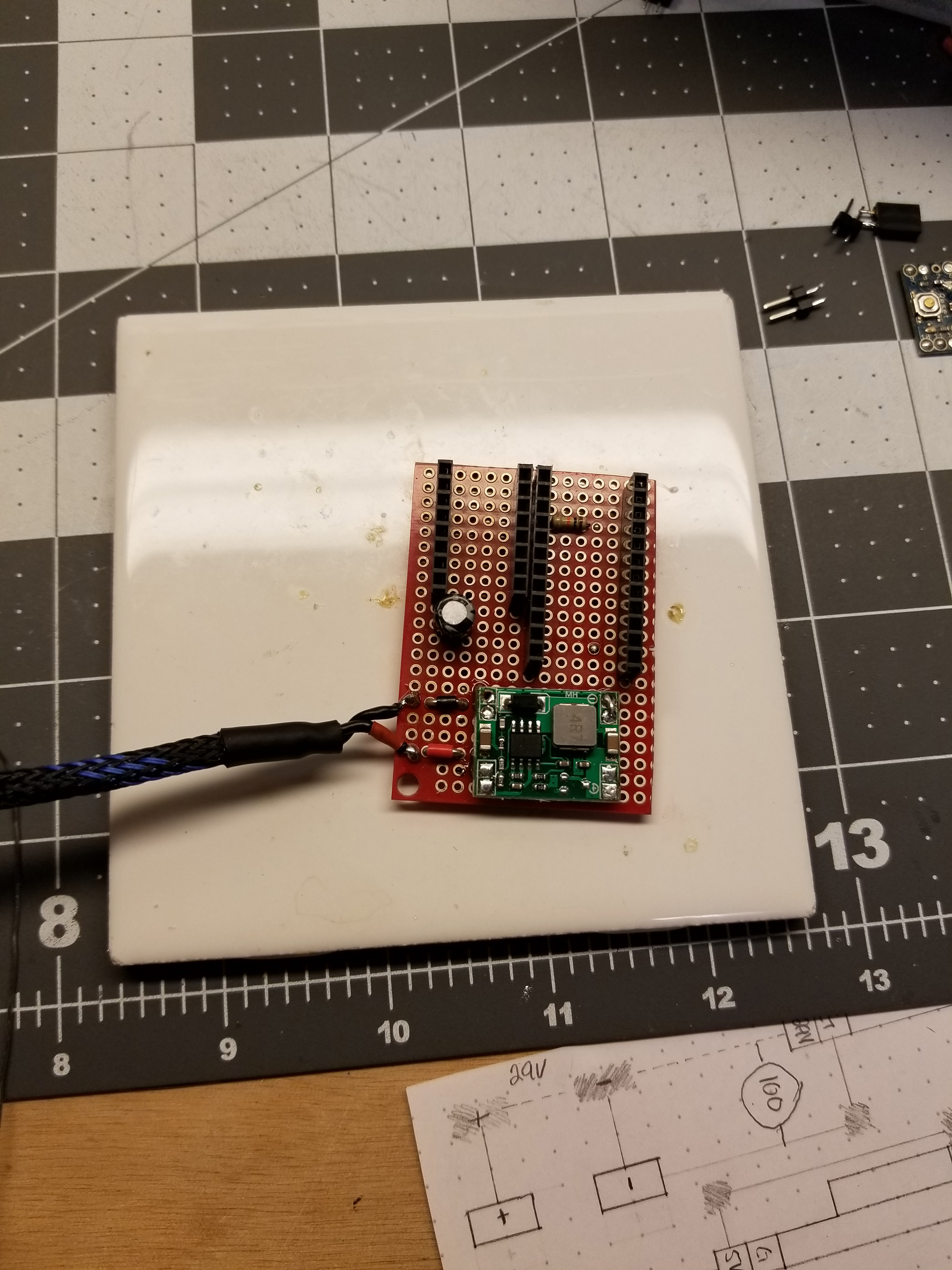
For power I have 29V DC so I need something that can step that down. I found two buck modules that I found interesting. One based on the LM2596 and one on MP1584. I went with the MP1584 even though the listed maximum input voltage is 28V. I looked at the datasheet for the MP1584 and found that it lists an absolute maximum input voltage of 30 and I am not going to need anywhere near 3A to power a promini and the logic rails of the A4988.
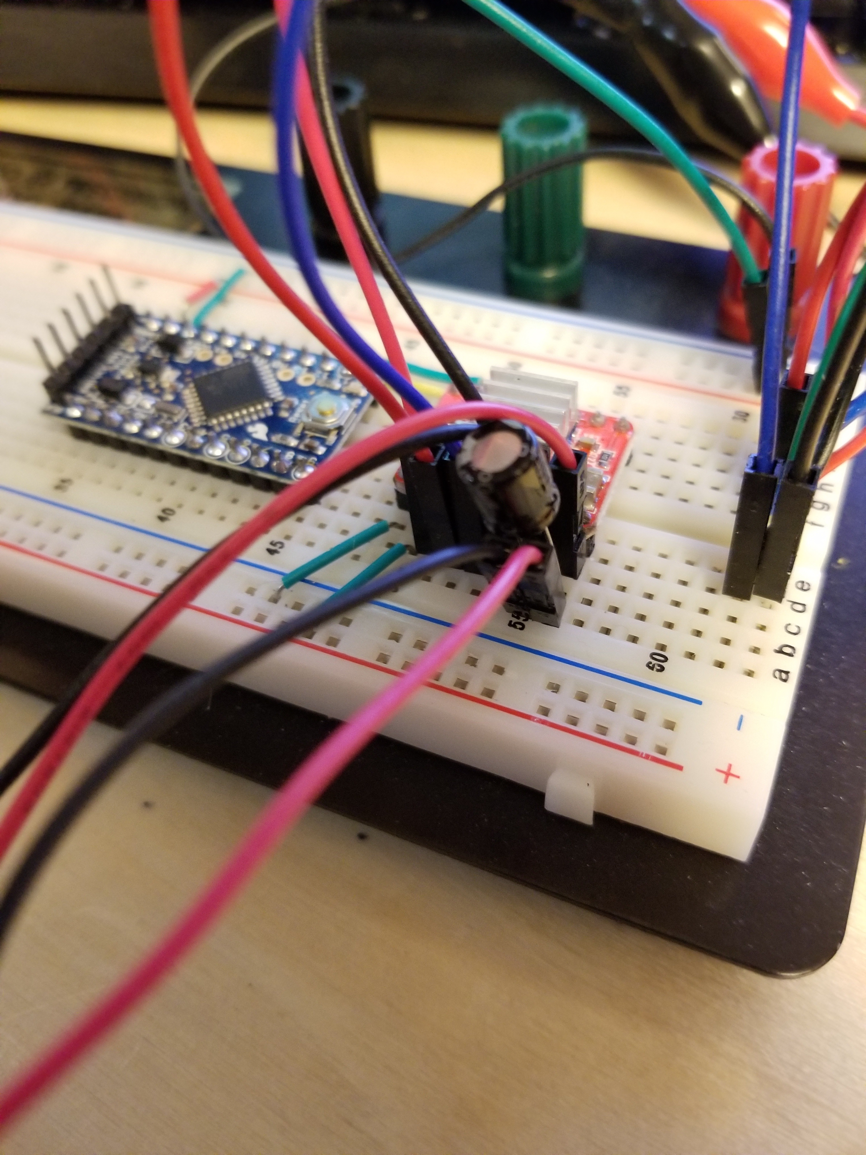

I did some testing on the bench with this setup and it seems to perform pretty well, driving the stepper motor for far longer periods of time than I will require for this project. The capacitor recommended by the A4988 product page is pretty neccesary.
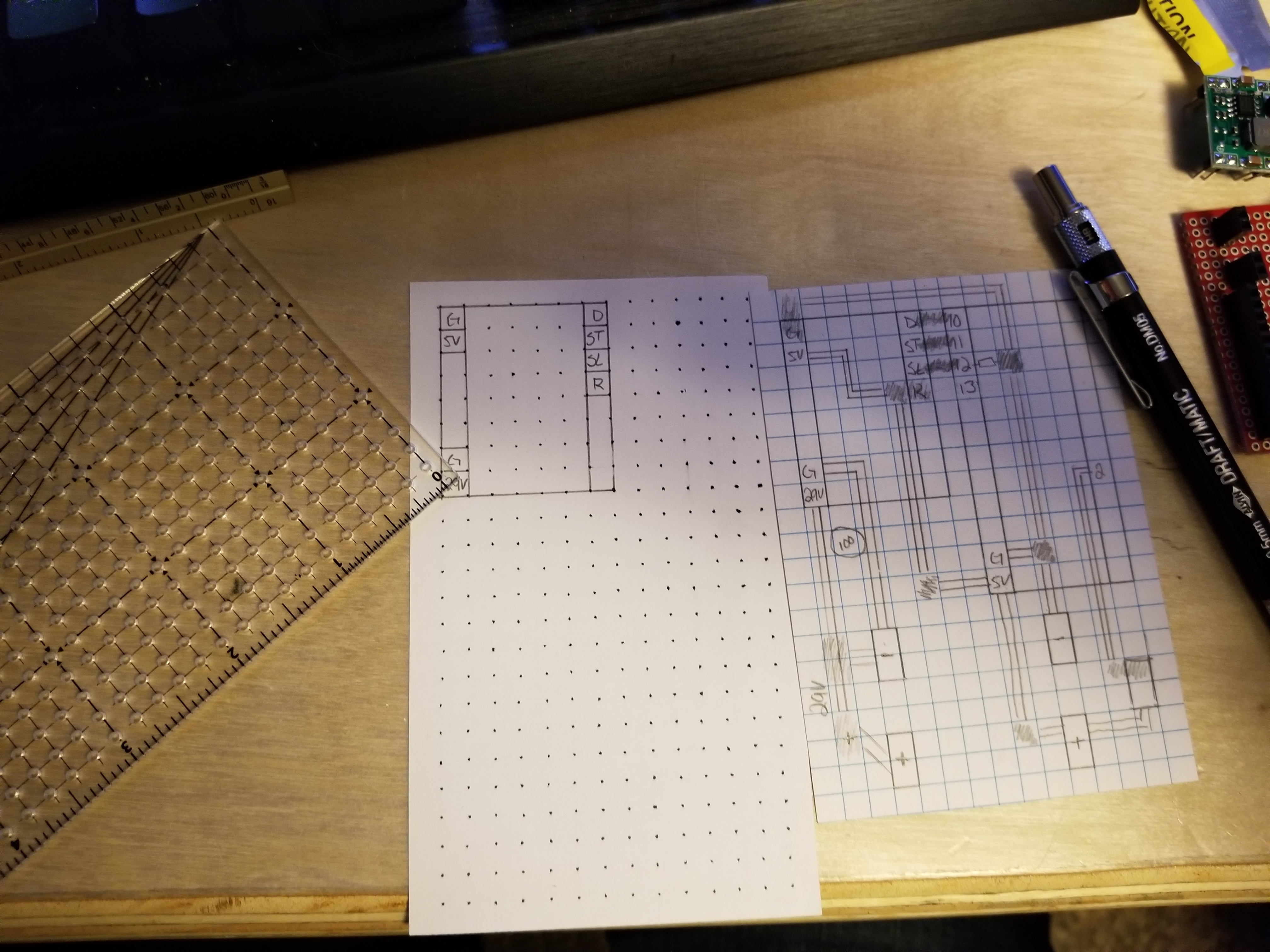
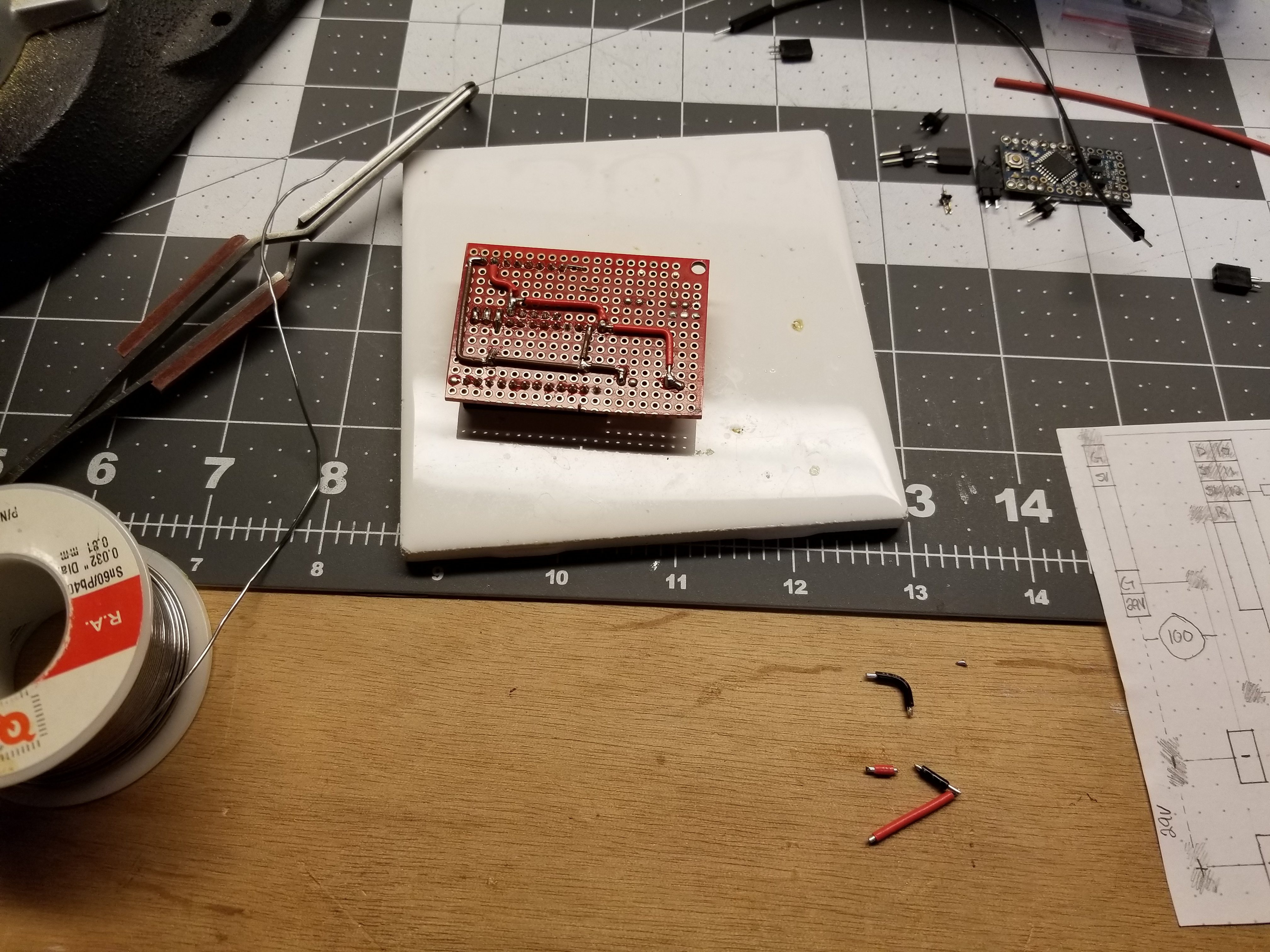
During this project I wanted to try out some new techniques. I haven’t done a circuit layout on paper in quite a while so I went for it. I had to learn some old lessons like not to use a ball point pen. On a trip to get a new pencil I learned about dot grid. Apparently though, dot grid index cards are complicated to get your hands on (shoutout to this incredibly detailed blog post) so I made my own.

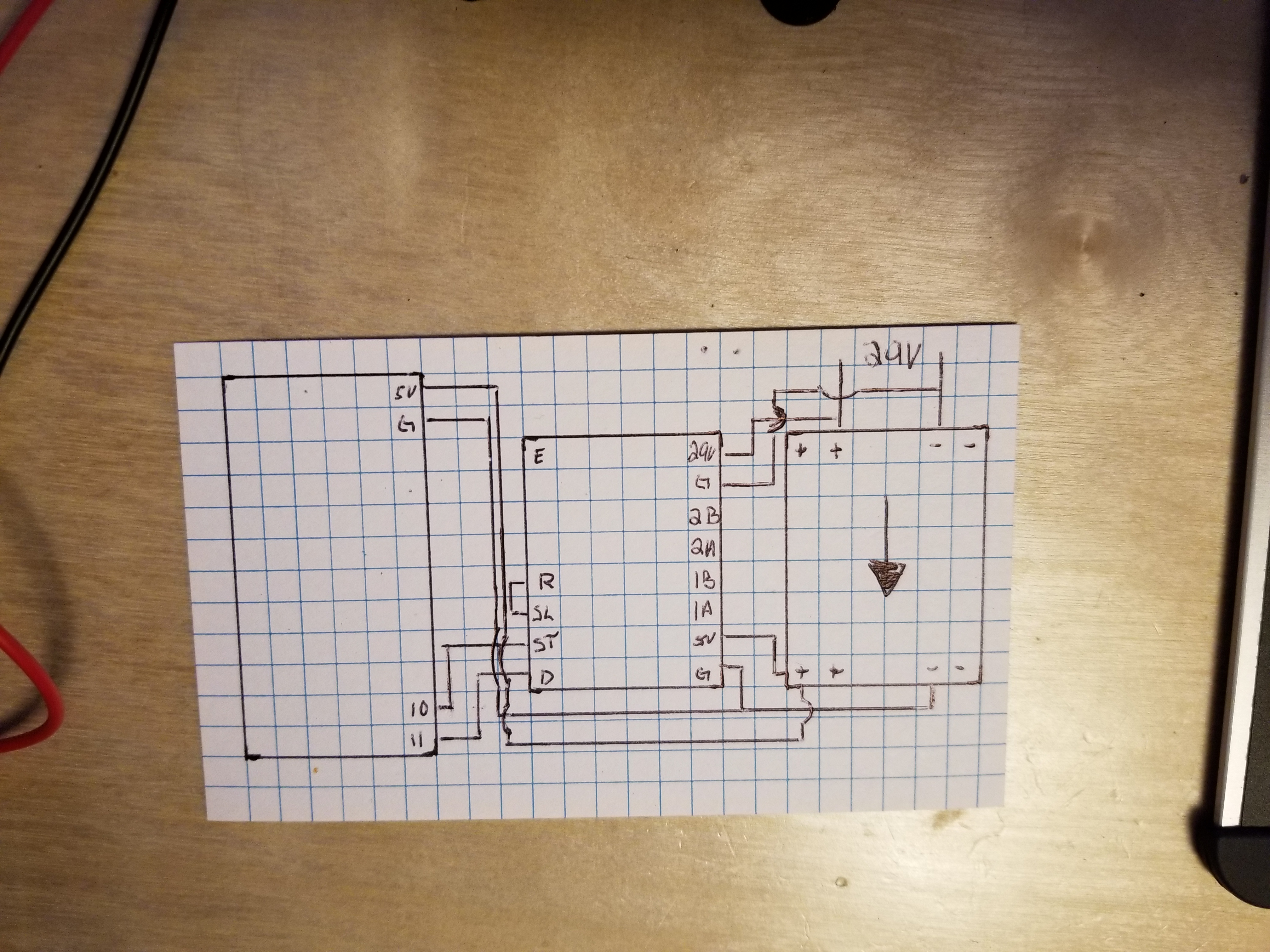

Power states
Figuring out how to control the power state of the A4988 wasn’t as straight forward as it could have been. The information in the datasheet is a bit spread out. I suggest setting Reset HIGH and leaving Enable floating. Then control the Sleep pin using a 10k pulldown resistor which is what I’ve done here.
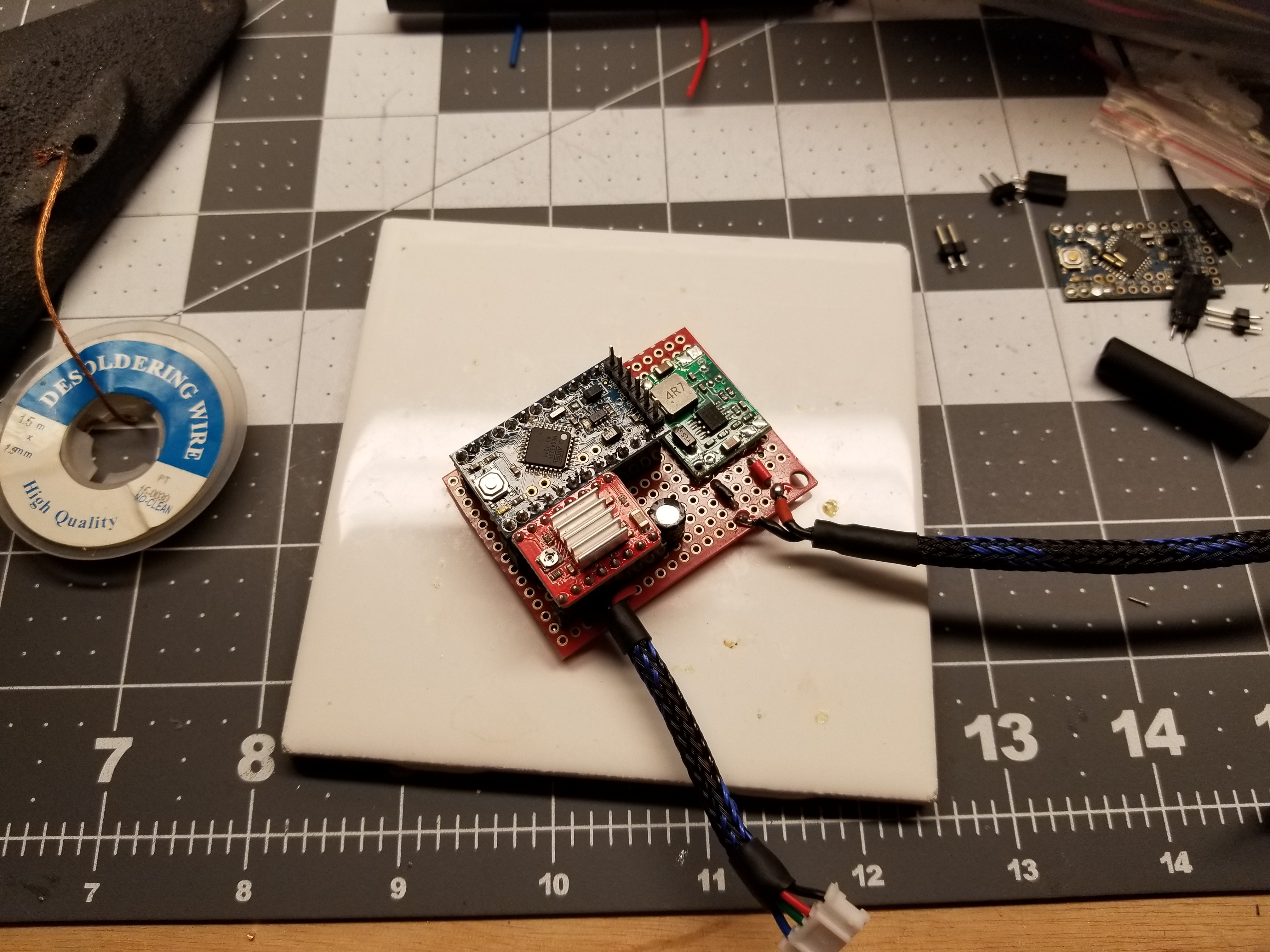
Main Build
I had a little trouble because this MP1584 wasn’t quite 0.1" pitch. :(
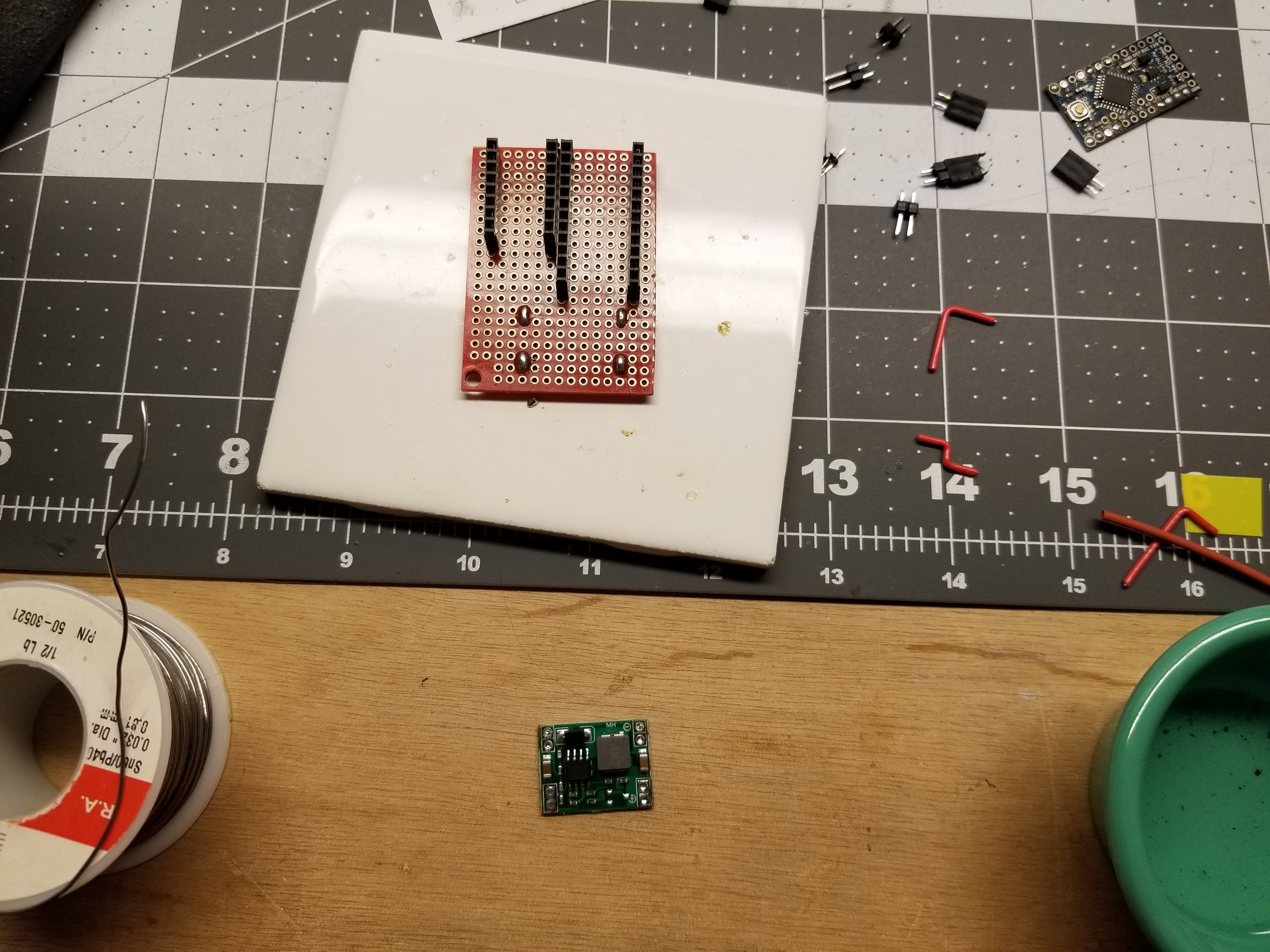
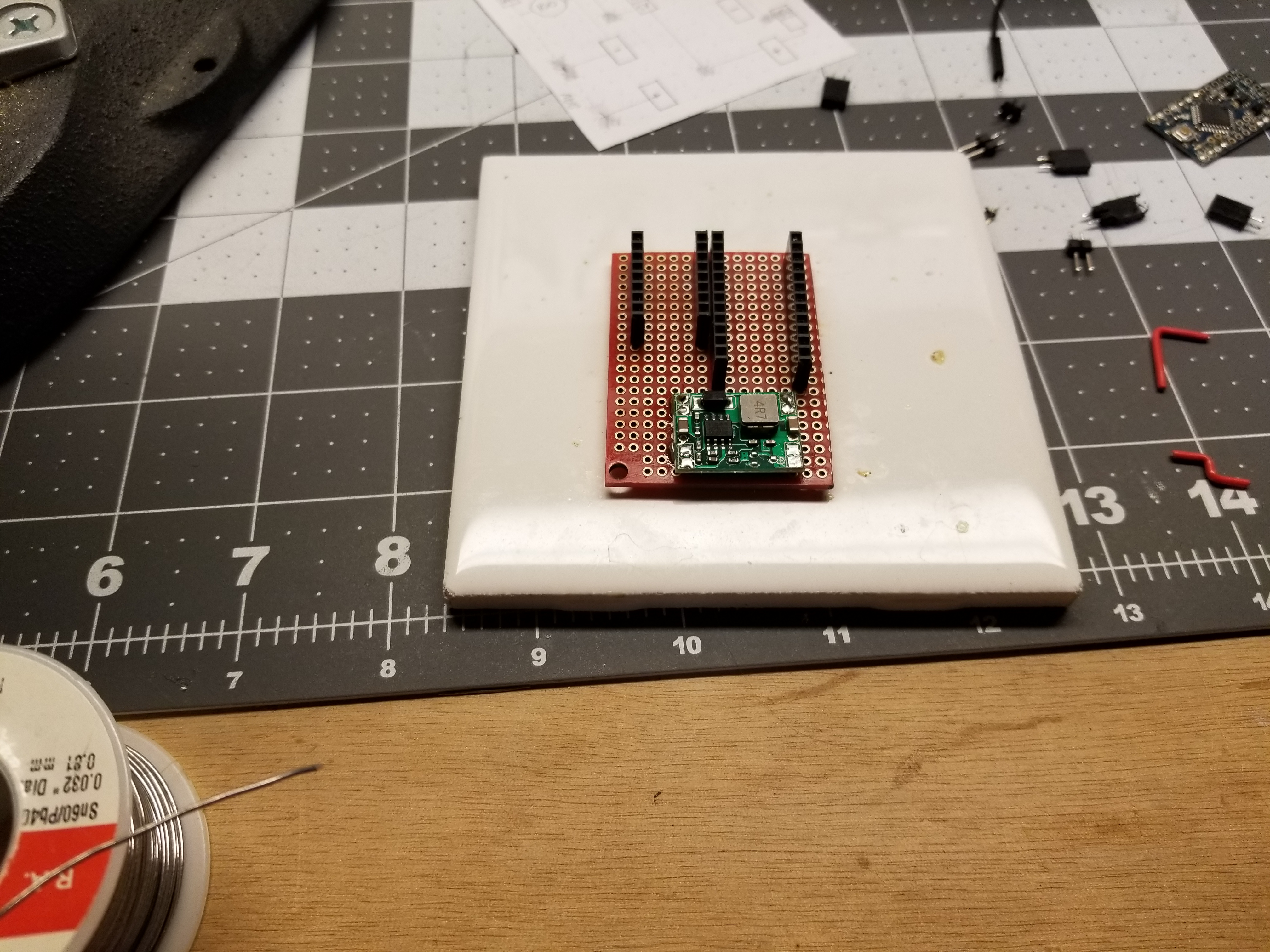
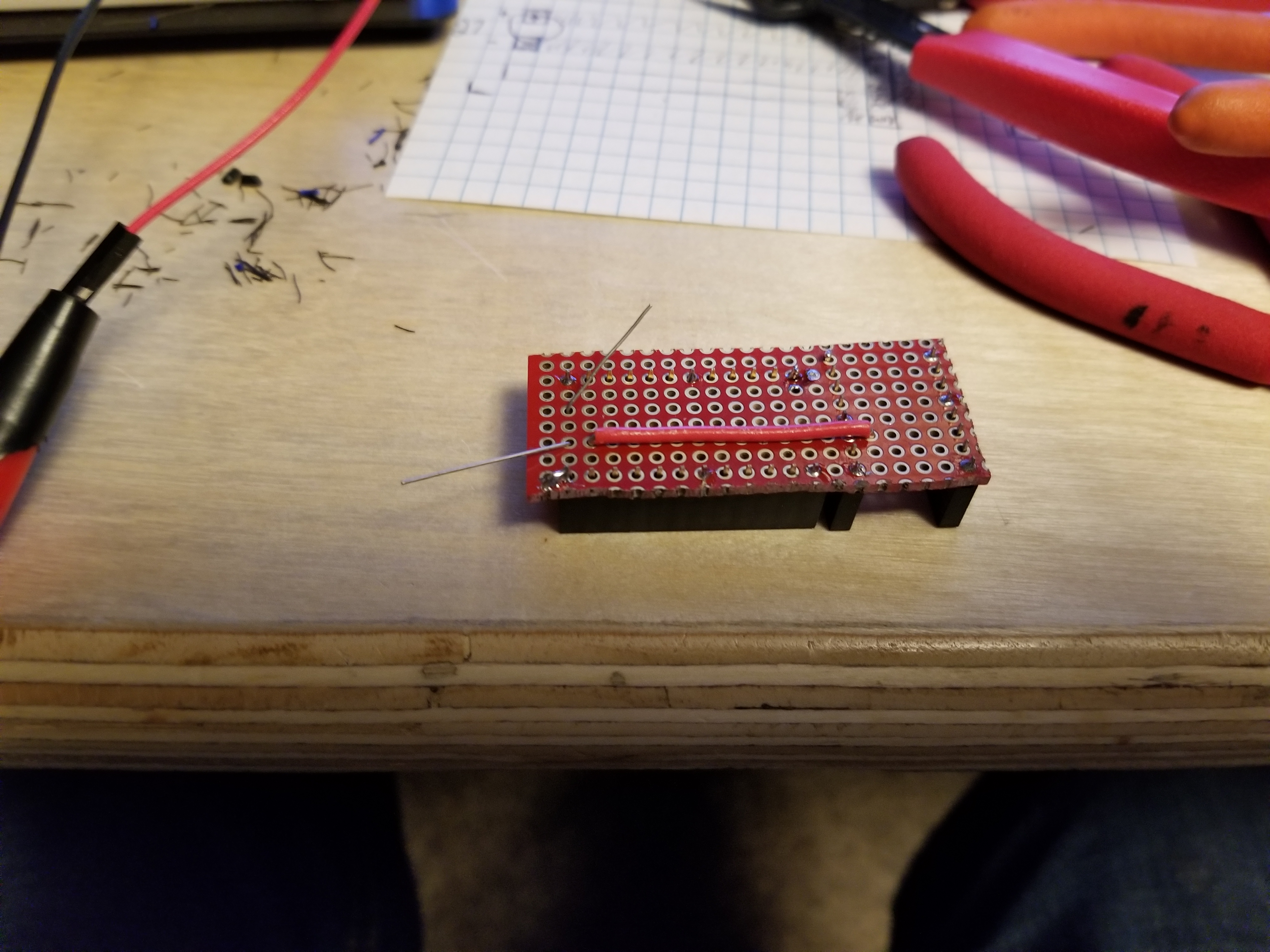
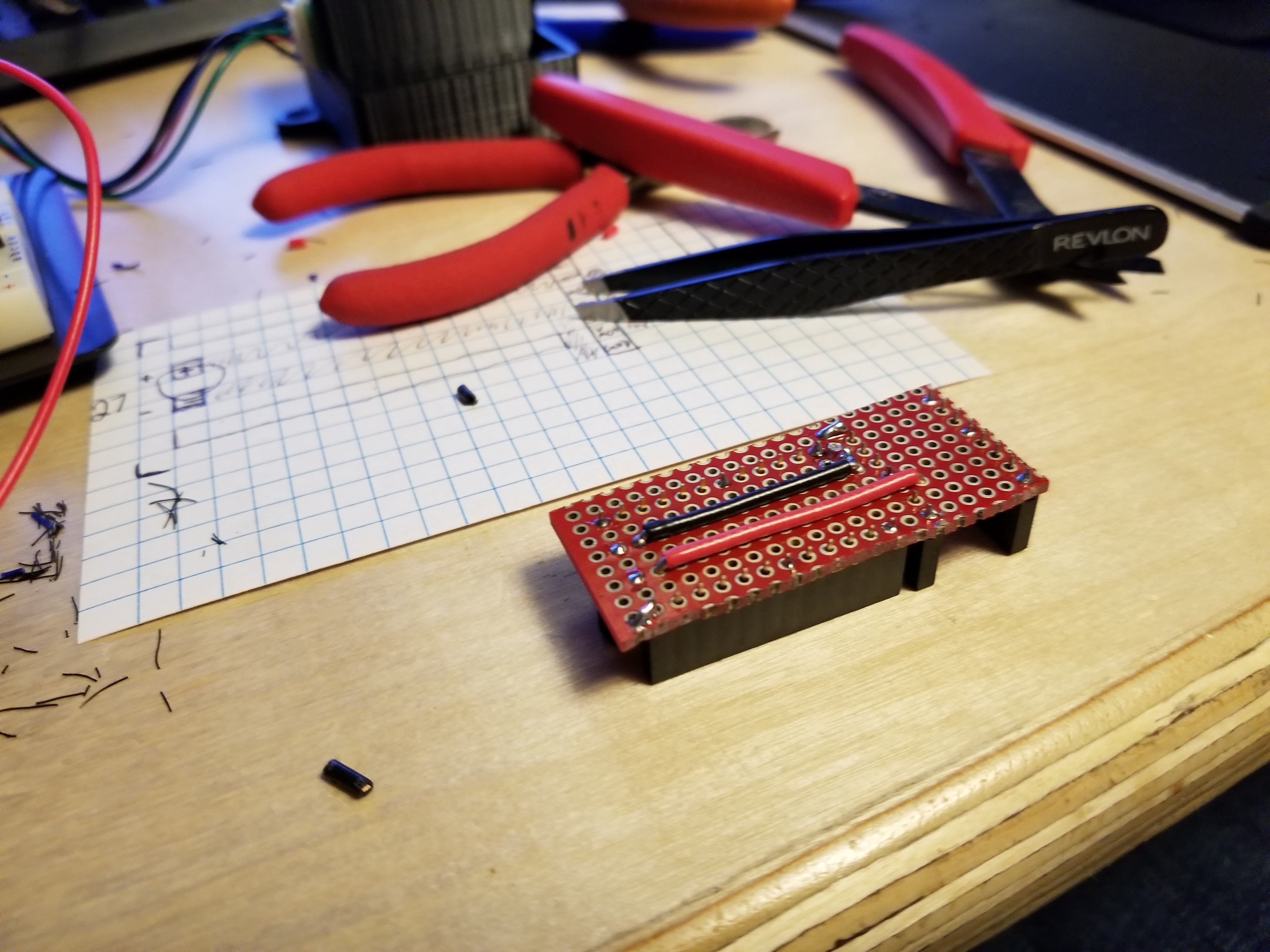
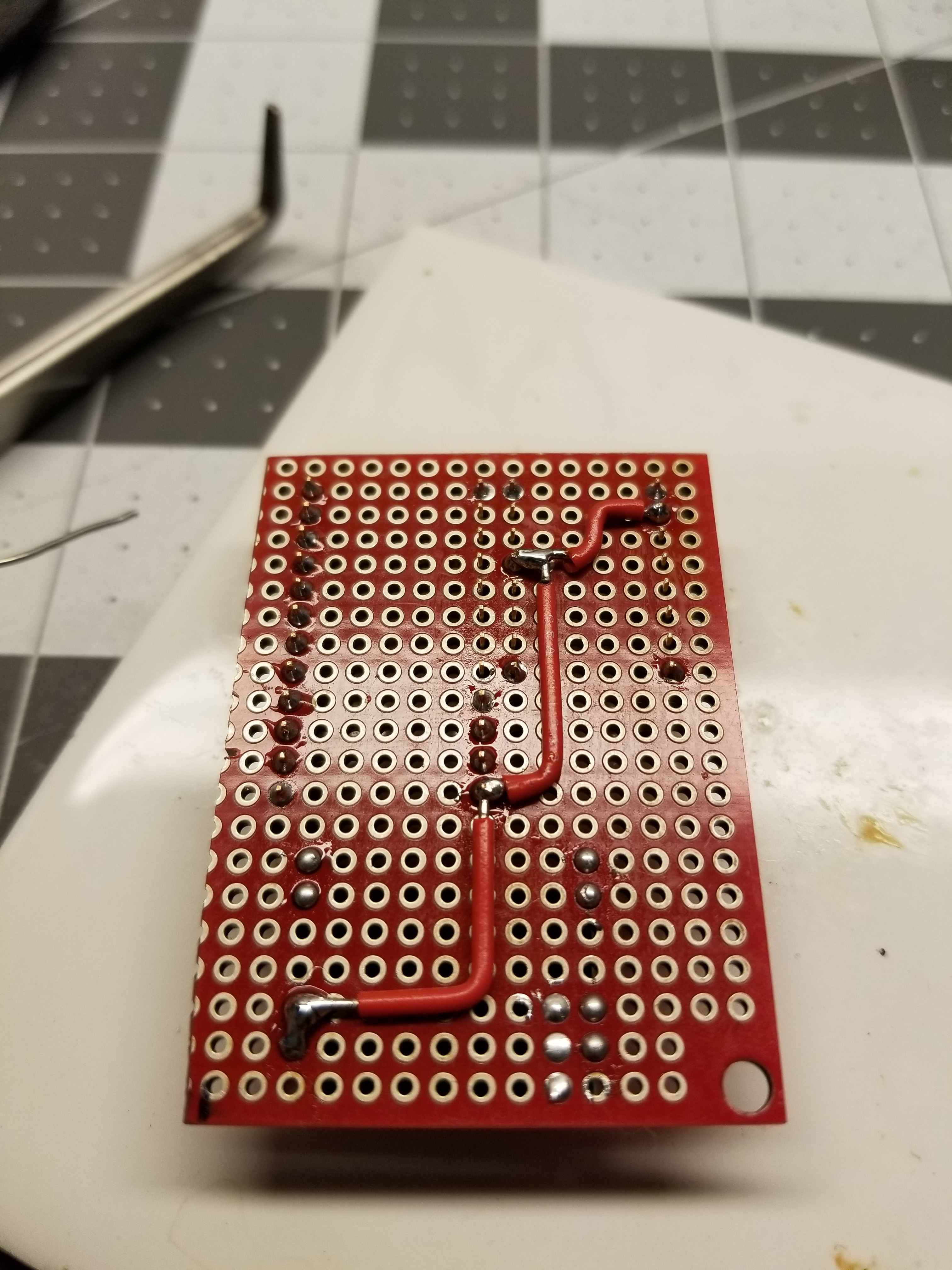
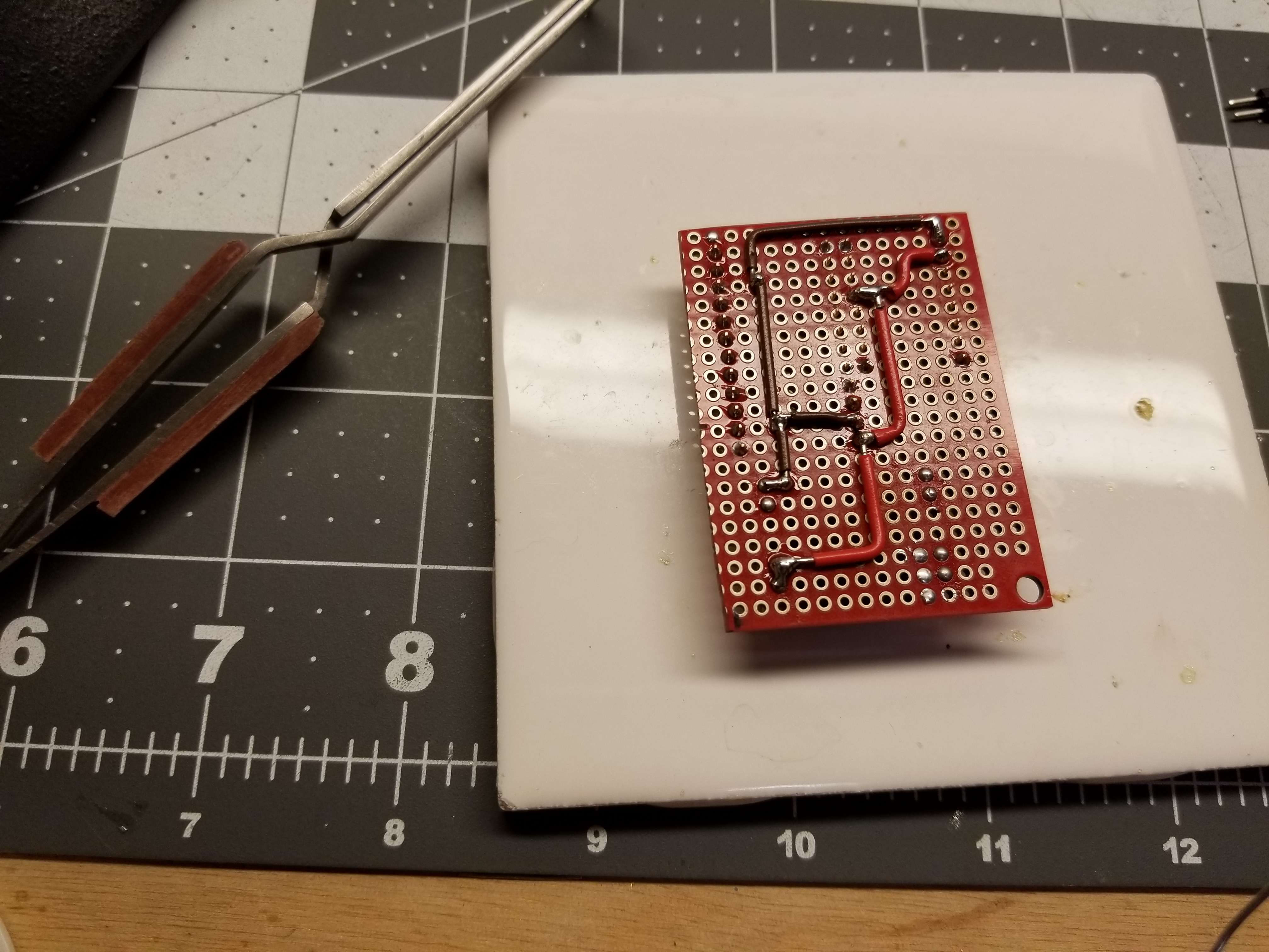
I normally build my circuit prototypes by bridging traces on a proto-pcb. For this one I wanted to just try making perfectly sized wire segments.
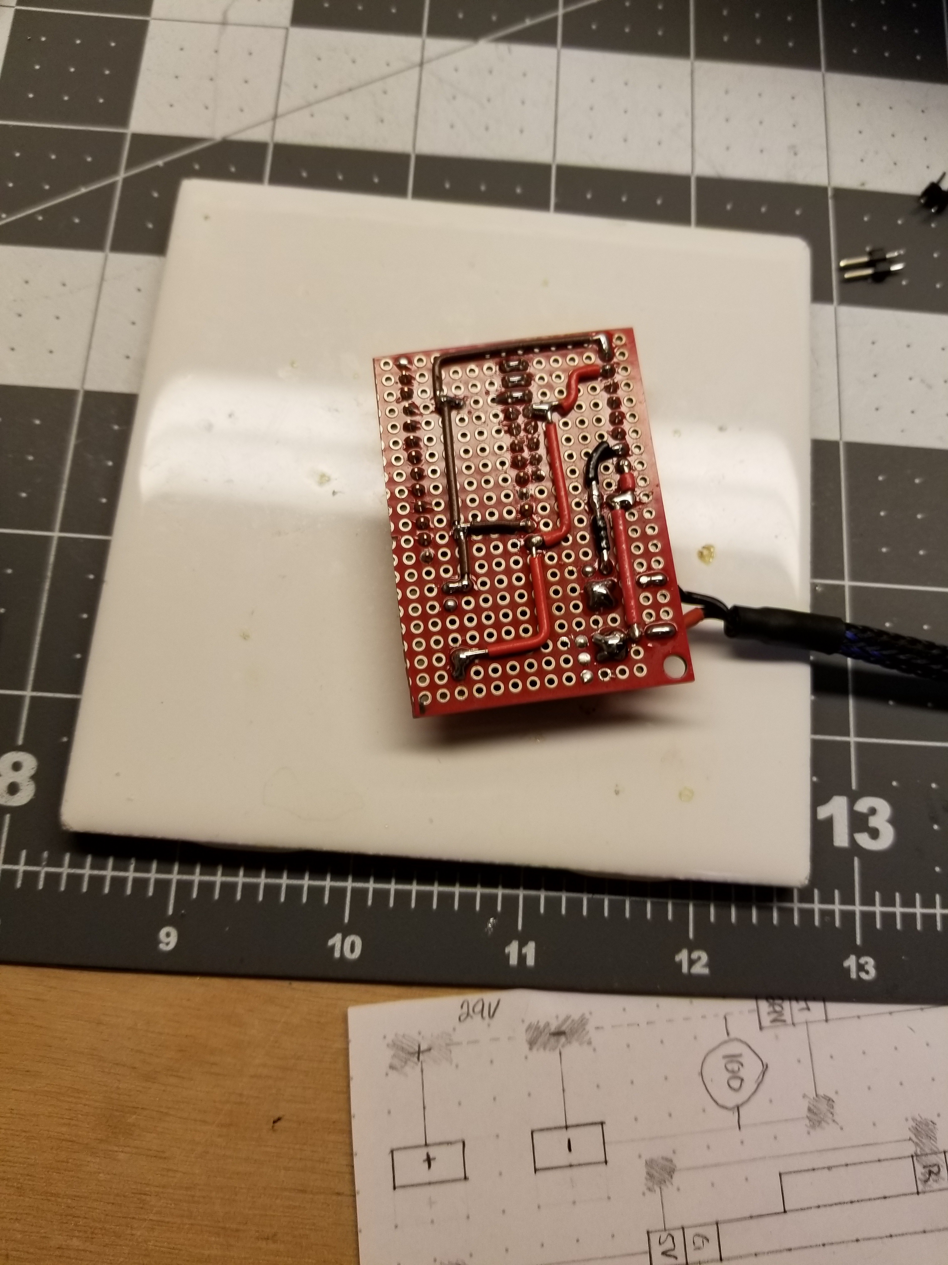
Finished
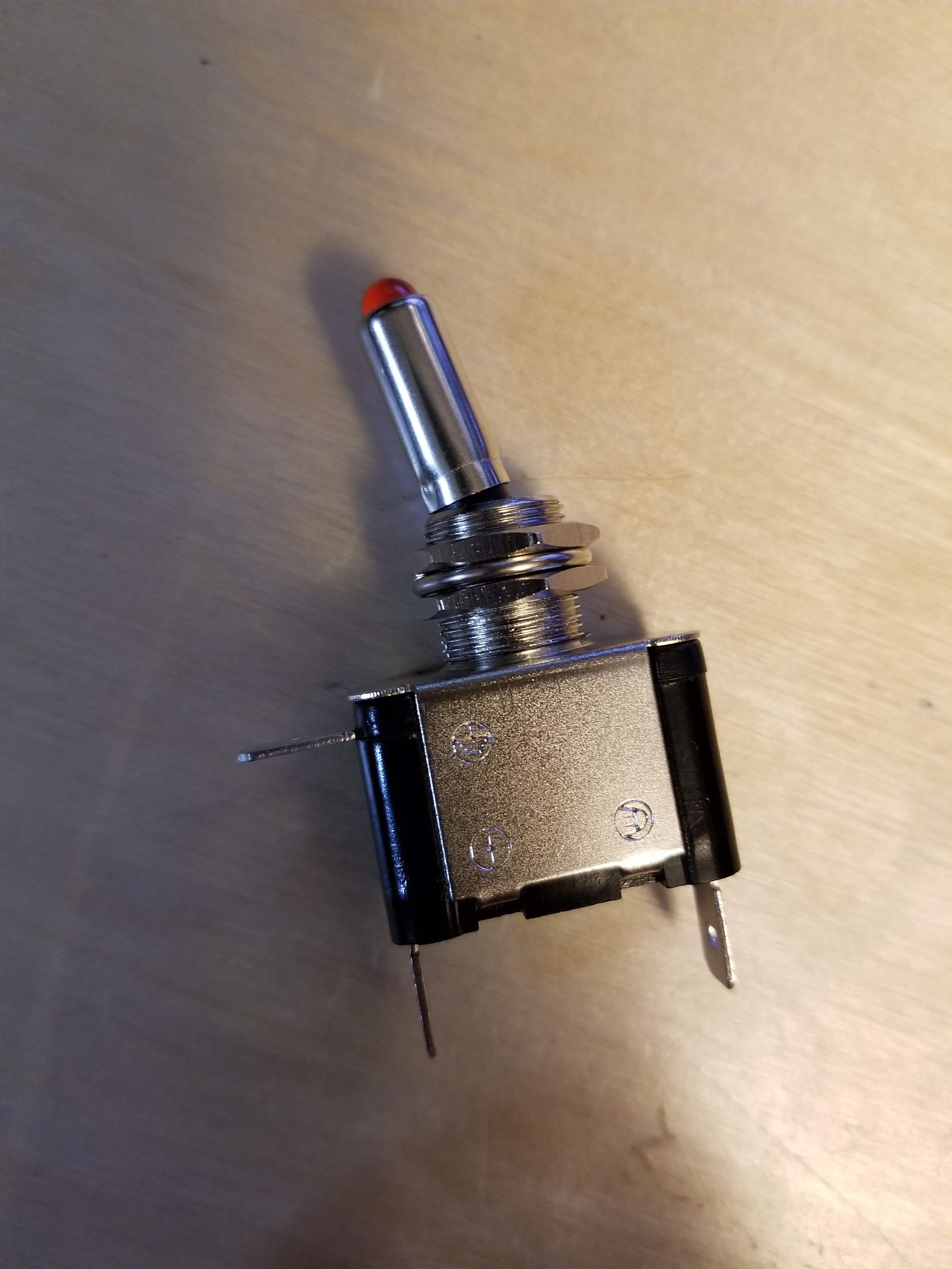
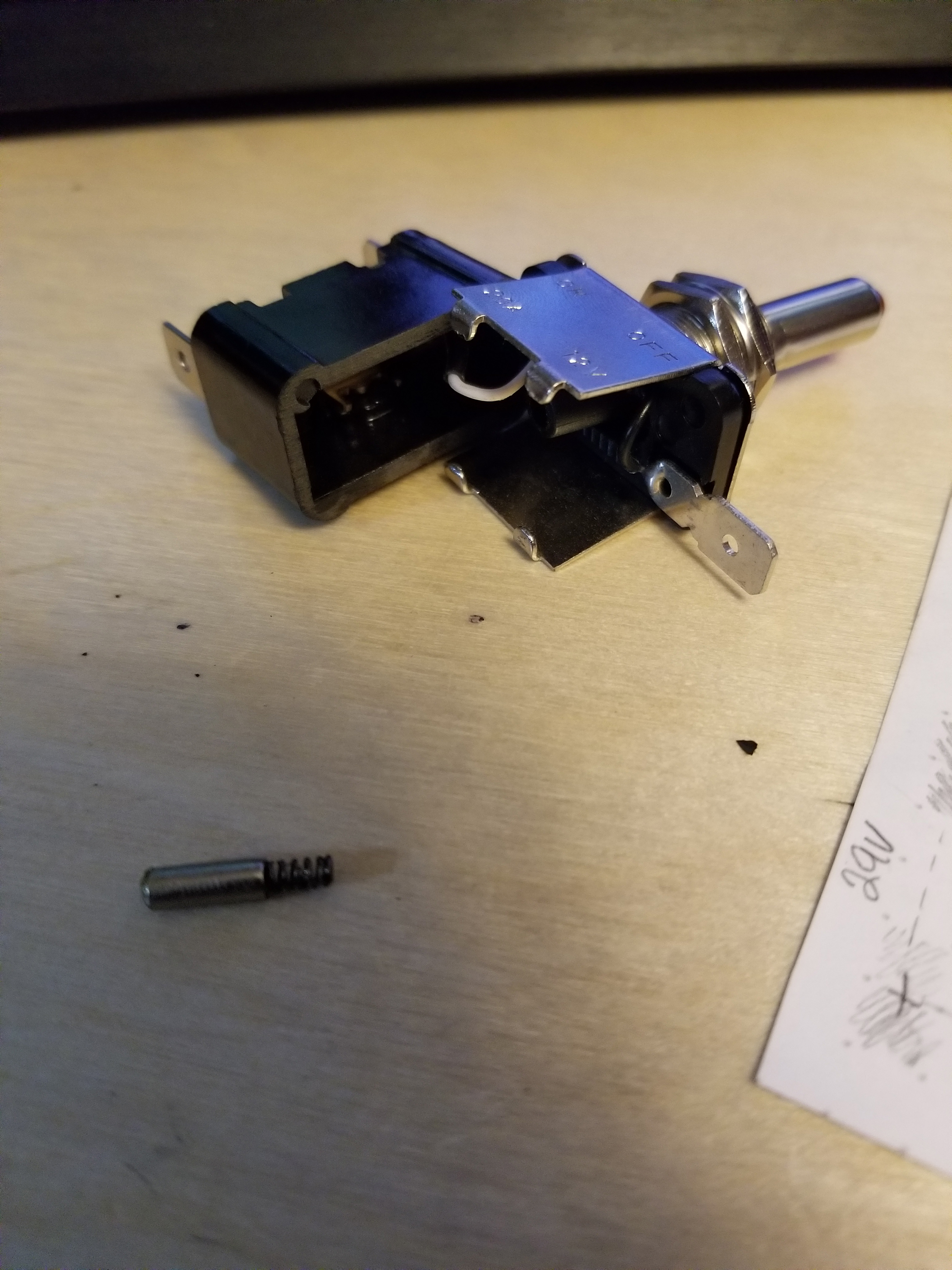
Illuminated Automotive Switch
As a bonus, I took apart the switch I am considering using. I found that if you swap the output/power terminals on your standard automotive illuminated switch the led will be on regardless of the switch position, which is actually what I was looking for with this project.

Thank you
Your comment has been submitted and will be published once it has been approved.
OOPS!
Your comment has not been submitted. Please go back and try again. Thank You!
If this error persists, please open an issue by clicking here.
Say something